AI Weld Inspection: Detecting Defects with Computer Vision
How AI weld inspection finds porosity, cracks and lack of fusion in images — and why uncertainty quantification matters in safety-critical work.
AI weld inspection uses computer vision to analyse images of welded joints and flag likely defects such as porosity, cracks, undercut and lack of fusion for a qualified inspector to review. It does not replace the inspector or the NDT programme behind them; it changes which welds get expert attention.
Weld inspection is the systematic examination of welded joints to confirm they meet the acceptance criteria set out in codes such as BS EN ISO 5817, and it is one of the areas where computer vision is now delivering practical value. An AI weld inspection system analyses images of welds — from production lines, site surveys or radiographic film — and flags likely defects such as porosity, cracks, undercut and lack of fusion for a qualified inspector to review. It does not replace the inspector or the NDT programme behind them; it changes where their time goes, from scanning thousands of acceptable welds to judging the small fraction that genuinely need expert attention.
This post covers what a vision system needs to detect, how AI fits alongside established visual and non-destructive weld testing, and why uncertainty-aware models matter when the weld sits in a nuclear island, a pressure system or a bridge deck.
Why does weld quality dominate safety-critical engineering?
Welds concentrate risk. They are where dissimilar geometry meets, where residual stress accumulates, and where most fatigue cracks in steel structures initiate. In nuclear plant, pressure vessels and pipework, weld integrity is central to the safety case: the Office for Nuclear Regulation expects licensees to reduce risks as low as reasonably practicable (ALARP), and demonstrating weld quality through inspection is a core part of that argument (onr.org.uk). In infrastructure, weld defects in bridges, gantries and rail structures are a recurring finding in principal inspections.
The inspection burden is correspondingly large. A single SMR module, wind-farm jacket or pipeline spread contains thousands of welds, each requiring at minimum a documented visual inspection, and many requiring volumetric NDT. Qualified welding inspectors (CSWIP, PCN) are scarce, their time is expensive, and the work is repetitive in exactly the way that erodes human consistency over a long shift. That combination — high volume, high consequence, scarce experts — is the profile where computer vision inspection earns its keep.
Which weld defects must a vision system find?
Weld defect terminology is standardised in BS EN ISO 6520, with acceptance limits for arc-welded steel joints defined by quality levels B, C and D in BS EN ISO 5817 (iso.org). The defects most relevant to image-based detection are:
Porosity. Gas pores trapped in solidifying metal, appearing as rounded dark spots on the surface or in radiographs. Scattered, clustered or aligned porosity carry different acceptance limits.
Cracks. The most serious class — hot cracks, cold (hydrogen) cracks, crater cracks. Almost never acceptable at any quality level, and often fine enough that they are easy to miss visually.
Lack of fusion and lack of penetration. The weld metal fails to fuse with the parent material or fill the joint root. Frequently subsurface, but detectable at the surface in fillet welds and in radiographic images.
Undercut. A groove melted into the parent metal at the weld toe, left unfilled. A classic fatigue initiator, and well suited to visual detection because it lives on the surface profile.
Slag inclusions and spatter. Trapped non-metallic material within the weld, and molten droplets adhering beside it. Spatter is cosmetic in some codes and rejectable in others; inclusions matter structurally.
Geometric imperfections. Excess reinforcement, misalignment (linear or angular), incorrect leg length on fillets. These are measurable quantities, which makes them natural targets for automated measurement rather than subjective judgement.
The point of listing these is that a useful weld defect detection system cannot be a single "defect / no defect" classifier. Acceptance depends on defect type, size, position and the applicable quality level — so the model output needs to be typed, localised and measurable, which is why detection and segmentation approaches beat whole-image classification for this task.
How welds are inspected today
Visual weld inspection comes first, always. BS EN ISO 17637 specifies visual testing of fusion-welded joints: surface condition, weld geometry, and surface-breaking imperfections, inspected directly or with aids such as boroscopes and mirrors. It is cheap and fast, which is why it gates everything else — there is no point radiographing a weld that fails visually.
For volumetric and subsurface examination, the established non destructive weld testing methods take over: radiographic testing for volumetric imperfections, ultrasonic testing (increasingly phased-array) for planar defects, and magnetic particle or dye penetrant inspection for surface-breaking indications on ferritic and non-ferritic steels respectively. The British Institute of Non-Destructive Testing sets out method selection and personnel certification routes (bindt.org). We covered how these methods relate to computer vision in Non-Destructive Testing Meets AI.
Two things are worth noticing about this workflow. First, several of its stages already produce images — visual survey photographs, digital radiographs, thermographic frames — that today are reviewed entirely by eye. Second, the review is the bottleneck: film interpretation and photographic review are slow, fatiguing, and dependent on a small pool of qualified people whose time is often the schedule-critical resource on an outage or a construction programme.
Where computer vision fits
AI weld inspection applies most directly at those image-review stages:
Production and site visual inspection. Cameras on a welding cell, a crawler, or an inspector's tablet capture the weld cap and toes. A detection model flags porosity, undercut, spatter, surface cracks and profile problems, and measures what can be measured. This is the same pattern as general automated visual inspection, specialised to weld features.
Radiograph triage. Digital radiographs are screened by a model that highlights indications and ranks films by likelihood of a rejectable defect, so interpreters spend their time on the films that matter. The interpreter remains the decision-maker — the model changes the order and focus of review, not the authority behind it.
Remote and hazardous locations. Where the weld is inside a vessel, on a subsea jacket or in a radiologically controlled area, images collected by ROV, drone or crawler can be assessed without repeat access — a theme we will return to in a later post on remote visual inspection in nuclear environments.
What three problems stall weld-inspection AI?
Most weld-inspection AI projects fail for the same three reasons, and they are worth being blunt about.
1. Labelled weld-defect data is scarce
Public weld datasets are small, and your welds — your processes, materials, surface finishes and camera setups — will not look like anyone else's. The classical approach demands thousands of labelled defect examples before it produces anything. VisionEngine starts from the opposite end: an open-vocabulary detection and segmentation baseline that responds to text prompts such as "porosity", "undercut" or "crack along weld toe" with zero project-specific training data. The baseline will not be perfect, but it exists on day one, on your images, and gives you something concrete to correct rather than a blank annotation queue.
2. Expert labelling time is the true cost
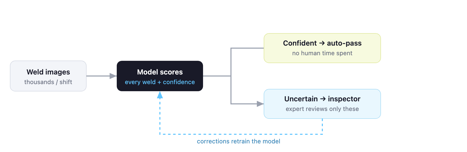
The people qualified to label weld defects are the same scarce inspectors the system is meant to relieve — paying them to draw boxes around ten thousand pores is a poor trade. Active learning inverts this: the model asks for labels only on the images where its uncertainty is highest, which are precisely the examples that improve it fastest. In practice this cuts the labelled-image requirement dramatically compared with labelling everything, an approach described in Active Learning for Computer Vision. A worked example on a public weld-defect dataset is coming later in this series.
3. Safety-critical work needs calibrated confidence
A model that outputs "crack: 0.93" is only useful if that number means something. In a nuclear or pressure-systems context, the operative question is never "what did the model say?" but "when should a human look?". VisionEngine attaches uncertainty quantification to every prediction, so the workflow can be built around risk: high-confidence acceptable welds pass with an audit trail, high-confidence defects go straight to the repair queue, and the genuinely uncertain cases — and only those — are routed to a qualified inspector. That routing rule, rather than raw accuracy, is what makes the system defensible in an ALARP argument: the human effort concentrates where the model itself declares doubt.
A practical workflow
A realistic first pass with VisionEngine on weld imagery looks like this:
- Upload a representative set of weld images — a few hundred is plenty to start, and no labels are needed.
- Baseline with open-vocabulary prompts for the defect classes in your acceptance criteria. Review what the zero-shot model finds and misses.
- Review the images the system is least certain about; your inspectors correct or confirm labels on that small, targeted set.
- Train an adapted model on those few labels, re-check the uncertainty profile, and repeat until the review burden matches the risk appetite of your quality plan.
Each cycle is measured in hours, not months, and every human decision is logged — which matters when the output feeds a quality record.
What AI weld inspection is not
It is not a replacement for qualified welding inspectors, for procedure qualification, or for volumetric NDT where the code requires it. A vision model sees what the sensor sees: surface imagery, or the radiographic/thermal image put in front of it. Subsurface lack of fusion in a thick section still needs ultrasonics; personnel certification and acceptance decisions still sit with people. The honest claim is narrower and more valuable — AI removes the repetitive scanning work from image review, makes the review consistent across shifts and sites, and gives you a defensible, quantified basis for deciding which welds get expert eyes.
For nuclear, energy and infrastructure teams, that translates to fewer inspector-hours per weld, faster feedback to welders while the fault is still correctable, and an inspection record in which every automated decision carries a confidence you can audit.
If you want to see this running on weld imagery — including how the open-vocabulary baseline behaves before any training — book a 20-minute technical walkthrough.
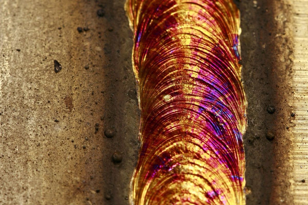
Hero image — Weld bead — Tanel Eensoo · CC BY-SA 3.0 · Wikimedia Commons.
Frequently asked questions
Can AI replace a qualified inspector?
No. AI weld inspection is a screening and review layer, not a replacement. It removes the repetitive scanning work, keeps review consistent across shifts, and routes uncertain cases to a person. Personnel certification, procedure qualification and acceptance decisions stay with qualified inspectors, with a human in the loop throughout.
How much labelled data do you need to start?
None to begin. VisionEngine starts from an open-vocabulary baseline that responds to text prompts such as "porosity" or "undercut" with no project-specific training data, so you get labelled results on your own weld images on day one. You then correct only the uncertainty-flagged examples to improve it.
What weld defects can computer vision detect?
Image-based models flag surface-visible defects such as porosity, undercut, spatter, surface cracks and geometric imperfections like misalignment or excess reinforcement, and can screen radiographs for indications. Because acceptance depends on defect type, size and position, the output is typed, localised and measurable rather than a single defect/no-defect verdict.
Why does uncertainty matter in safety-critical weld inspection?
In nuclear or pressure-systems work the operative question is when a human should look, not what the model said. VisionEngine attaches uncertainty quantification to every prediction, so confident acceptable welds pass with an audit trail, confident defects go to repair, and only genuinely uncertain welds reach a qualified inspector — a defensible basis for an ALARP argument.