Bridge Inspection with Computer Vision: Cracks & Corrosion
How automated bridge inspection with computer vision finds cracks and corrosion in drone imagery, with uncertainty-aware review for engineers.
Automated bridge inspection with computer vision uses trained models to detect, localise and measure visible defects — cracks, corrosion, spalling — in drone and inspection imagery, producing a structured defect record that engineers review and grade. It makes each inspection faster and more consistent; it does not replace the structural inspection regime.
Automated bridge inspection uses computer vision to detect and map defects — cracks, corrosion, spalling, vegetation ingress — from photographs and drone imagery, so that engineers spend their time judging condition rather than hunting for defects frame by frame. It does not replace the structural inspection regime; it makes each inspection faster, more consistent and better documented. For UK bridge owners managing thousands of structures against fixed inspection cycles and tight maintenance budgets, that combination is increasingly hard to ignore.
This pillar guide explains how automated bridge inspection works end to end: what the UK inspection regime requires, how drone bridge inspection changes data capture, which defects computer vision can reliably detect, and why uncertainty quantification matters when the output feeds safety-critical decisions.
What is automated bridge inspection?
Automated bridge inspection is the use of computer vision models to analyse inspection imagery — from drones, telescopic cameras, rope-access photography or handheld capture — and automatically detect, localise and measure visible defects such as cracks, corrosion and spalling. The output is a structured defect record tied to locations on the structure, which an engineer then reviews and grades.
The word "automated" earns its place at the analysis stage, not the judgement stage. A model can find every visible crack in ten thousand images overnight; deciding whether a particular crack indicates bearing movement or simple shrinkage remains an engineering call. The best implementations are explicit about this split, and route their output into the existing inspection and assessment process rather than around it.
Where does automation fit in the UK bridge inspection regime?
Highway structures in the UK are inspected under CS 450 in the Design Manual for Roads and Bridges, which sets out the familiar cycle: General Inspections roughly every two years, covering all parts of the structure that can be seen without special access, and Principal Inspections roughly every six years, requiring close examination — within touching distance — of all inspectable parts (Standards for Highways). Network Rail runs an analogous regime of visual and detailed examinations across its portfolio of bridges, viaducts and culverts.
Two features of this regime make it a natural fit for computer vision. First, it already generates imagery at scale: a single Principal Inspection of a medium-span structure can produce thousands of photographs, and drone-assisted surveys multiply that number. Second, it demands consistency over time — an inspector in 2026 must be able to compare condition against the record from 2020, ideally defect by defect. Humans are good at spotting defects and poor at doing so consistently across years, teams and weather conditions. Models are the reverse of neither: they are consistent by construction, and their detection performance is measurable.
Automation therefore slots in at three points: triaging imagery after capture so engineers review the frames that matter; producing a consistent, queryable defect record; and flagging change between inspection cycles.
How is drone bridge inspection changing data capture?
Drone bridge inspection has moved from novelty to routine for many asset owners, and it changes the economics of data capture dramatically. Soffits, bearing shelves, high piers and areas over water or live traffic — the places that traditionally required scaffolding, under-bridge units or rope access — can often be photographed in a single flight session. That reduces cost, programme time and, importantly, inspector exposure to working at height and over live carriageways.
The catch is volume. A drone survey of a single structure routinely returns several thousand high-resolution images, and a portfolio-wide programme returns millions. Nobody reviews millions of images manually with consistent attention; in practice, unaided review means sampling, and sampling means missed defects. This is precisely the gap computer vision fills: every frame gets the same scrutiny, and the human effort concentrates on the frames the model flags.
Good capture practice still matters. Consistent stand-off distance, overlapping coverage and a known ground sampling distance are what let a model convert pixel measurements into physical crack widths and corrosion areas. Where surveys are photogrammetric, detections can be projected onto a 3D model of the structure, turning per-image findings into a spatial defect map. A dedicated guide to processing drone survey data will follow later in this series.
What can computer vision detect on bridges?
Crack detection
Cracks are the highest-value target and the most studied. Modern segmentation models trace crack paths at pixel level, which allows automatic estimation of crack width, length and orientation once the image scale is known. That matters because crack width thresholds drive engineering response — hairline shrinkage cracking in concrete is usually cosmetic, while wider or propagating cracks demand investigation.
The hard cases are the ones every inspector knows: cracks disguised by surface staining, hairline cracks at the limit of image resolution, and crack-like false positives from joints, shadows, tie-holes and cables. This is exactly where model confidence becomes operationally important, as covered below. A deeper treatment of concrete crack detection and grading follows later in this series.
Corrosion and steelwork defects
Corrosion presents differently from cracking: it is a texture-and-colour problem rather than a line-tracing problem, and it shades continuously from surface staining through active rust to section loss. Segmentation models can map corroded area on steelwork, bearings and parapets, and quantify the affected percentage of a member's visible surface — a useful, repeatable input to condition scoring. What vision alone cannot do is measure remaining section thickness; that remains the province of ultrasonic testing and other non-destructive testing methods, with imagery directing where to deploy them.
Spalling, exposed reinforcement and the rest
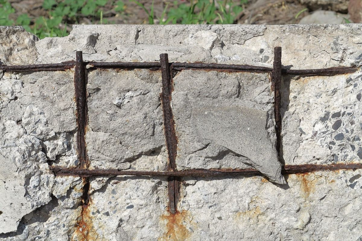
Beyond cracks and corrosion, models trained or prompted appropriately can pick out spalling and delamination, exposed and corroding reinforcement, water staining and leachate, vegetation ingress, damaged joints and drainage defects. On masonry structures, mortar loss and displaced units are detectable, though grading them is more subjective. The practical point is that a defect taxonomy can be built out incrementally — start with the defect types that drive your maintenance spend, and extend as the system proves itself.
The labelled-data problem — and how to start without labels
Here is where most bridge inspection AI projects historically stalled. Training a conventional detection model needs thousands of labelled examples per defect type, and labelling inspection imagery requires engineers who can tell spalling from staining — expensive people whose time the project was meant to save. Public crack datasets exist, but models trained on them transfer poorly to your structures, your camera setups and your defect definitions.
Open-vocabulary detection changes the starting point. Foundation models can now detect and segment objects from a plain-language description — "crack in concrete", "corrosion on steel girder", "exposed rebar" — with zero project-specific training data. The out-of-the-box accuracy will not match a mature trained model, but it produces a working baseline on day one, on your own imagery, before anyone has labelled anything. That baseline tells you two valuable things immediately: whether the defects you care about are visually detectable in your imagery at all, and where the model struggles.
This is the approach VisionEngine takes: upload inspection photographs, describe the defects in words, and get an instant open-vocabulary baseline to react to — as described in our guide to automated visual inspection.
From baseline to trained model with active learning
The route from that baseline to a production-grade model is not "label everything". Active learning inverts the labelling workflow: instead of engineers annotating images at random, the model identifies the images it is most uncertain about and asks for labels on those specifically. Each labelled image is chosen to be maximally informative, so accuracy climbs steeply with far fewer labels than conventional training demands.
For bridge inspection this fits operational reality unusually well. Senior inspection engineers cannot spend weeks drawing boxes, but they can review a short queue of genuinely ambiguous images — is this a crack or a joint? staining or corrosion? — a few minutes at a time. Their scarce judgement goes exactly where it changes the model most.
Uncertainty: the difference between a demo and a deployable system
Structural inspection is safety-critical work. A model that outputs "crack: yes/no" with no measure of confidence forces an unpalatable choice: trust it blindly, or re-check everything and gain nothing. The professional NDT community has been clear that the reliability of AI-assisted inspection must be demonstrated, not assumed — see the British Institute of Non-Destructive Testing on certification and capability in NDT (bindt.org).
Uncertainty quantification resolves the dilemma by making the model report how sure it is, detection by detection. High-confidence detections of routine defects flow straight into the condition record. Low-confidence cases — unusual textures, poor lighting, defect types at the edge of the training distribution — are routed to an engineer for review. The result is a defensible human-in-the-loop process: every flagged frame either passed a stated confidence threshold or was reviewed by a qualified person. That maps naturally onto the risk-based, ALARP-style reasoning UK infrastructure owners already apply, and it gives a technical approver something concrete to sign off: thresholds, review rates and detection performance, all measurable and auditable.
Calibration matters as much as the headline number: a model that says "90% confident" should be right about nine times in ten. Poorly calibrated confidence is worse than none, because it manufactures false assurance. When procuring any automated inspection system, ask how confidence is computed and how calibration is verified.
What a working automated bridge inspection workflow looks like
Putting the pieces together, a practical workflow for a UK bridge owner looks like this. Imagery arrives from drone surveys, principal inspection photography or routine site visits and is ingested against the structure's reference data. An open-vocabulary baseline model screens every frame for the agreed defect taxonomy on day one. Engineers review flagged frames, and their corrections feed an active learning loop that steadily trains a model specific to the portfolio's structures, camera setups and defect definitions. Uncertainty thresholds decide which detections auto-populate the defect record and which queue for human review. Each inspection cycle, detections are compared against the previous record, so change — a lengthening crack, a spreading corrosion patch — is surfaced explicitly rather than rediscovered.
None of this requires replacing the inspection regime, the condition scoring system or the asset management database. The model's output is structured data; it should land wherever your inspection records already live. Railway structures, tunnels and dams follow the same pattern with their own capture constraints, and later posts in this series will cover them directly.
Honest limitations
Computer vision reads surfaces. It will not find internal delamination, chloride ingress ahead of visible damage, fatigue cracking inside welded connections, or scour below the waterline — those need testing methods, monitoring or diving inspections, and imagery can only help target them. Detection quality is bounded by image quality: motion blur, poor lighting and excessive stand-off distance degrade models and humans alike. And a model trained on concrete highway bridges will need adaptation for masonry arches or riveted wrought-iron spans. Treat vendor claims that ignore these boundaries with suspicion.
Getting started
The pragmatic first step costs almost nothing: take a set of existing inspection photographs — last year's principal inspection, a recent drone survey — and run an open-vocabulary baseline against the defects you already log. Within an afternoon you will know how detectable your defect classes are, what the false-positive picture looks like, and where targeted labelling would pay off. From there, active learning and uncertainty-based review turn a promising baseline into a system your technical approvers can stand behind.
Run a free baseline on your inspection photos — upload imagery from your own structures and see what an uncertainty-aware model finds.
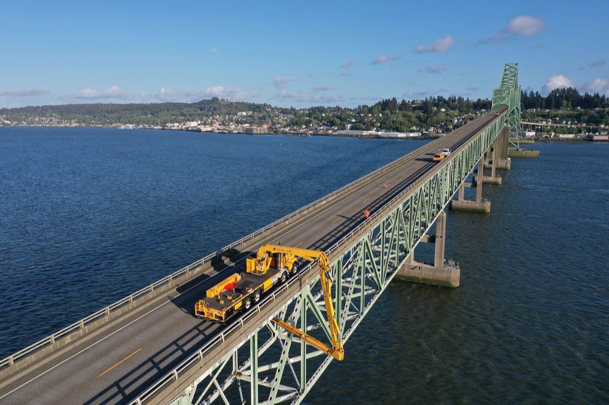
Hero image — Bridge inspection — Oregon Department of Transportation · CC BY 2.0 · Wikimedia Commons.
Frequently asked questions
Can AI replace a qualified inspector?
No. Computer vision automates defect detection and measurement, not engineering judgement. It screens every frame consistently and flags candidates, but deciding what a defect means for a structure remains a qualified inspector's call. The model acts as a consistency and screening layer inside a human-in-the-loop process, not a replacement.
How much labelled data do you need to start?
None. An open-vocabulary baseline detects defects from a plain-language description — "crack in concrete", "corrosion on steel" — with zero project-specific training data, so you get a working result on your own imagery on day one. Labelling then focuses on the uncertain images active learning surfaces, not on annotating everything.
Which bridge defects can computer vision reliably detect?
Segmentation models can trace cracks at pixel level and estimate width, length and orientation once image scale is known. They can map corrosion area on steelwork and flag spalling, exposed reinforcement, water staining, vegetation ingress and damaged joints. What imagery cannot measure — remaining section thickness, internal delamination — still needs testing methods.
Why does uncertainty matter in automated bridge inspection?
Structural inspection is safety-critical, so a detection needs a confidence measure, not just a yes/no. Uncertainty quantification lets high-confidence detections of routine defects flow into the record while low-confidence cases are routed to an engineer. Calibration matters: a model that says "90% confident" should be right about nine times in ten.