Concrete Crack Detection: Grading Cracks with AI
How computer vision handles concrete crack detection — measuring crack width, grading severity and routing only uncertain cracks to an engineer.
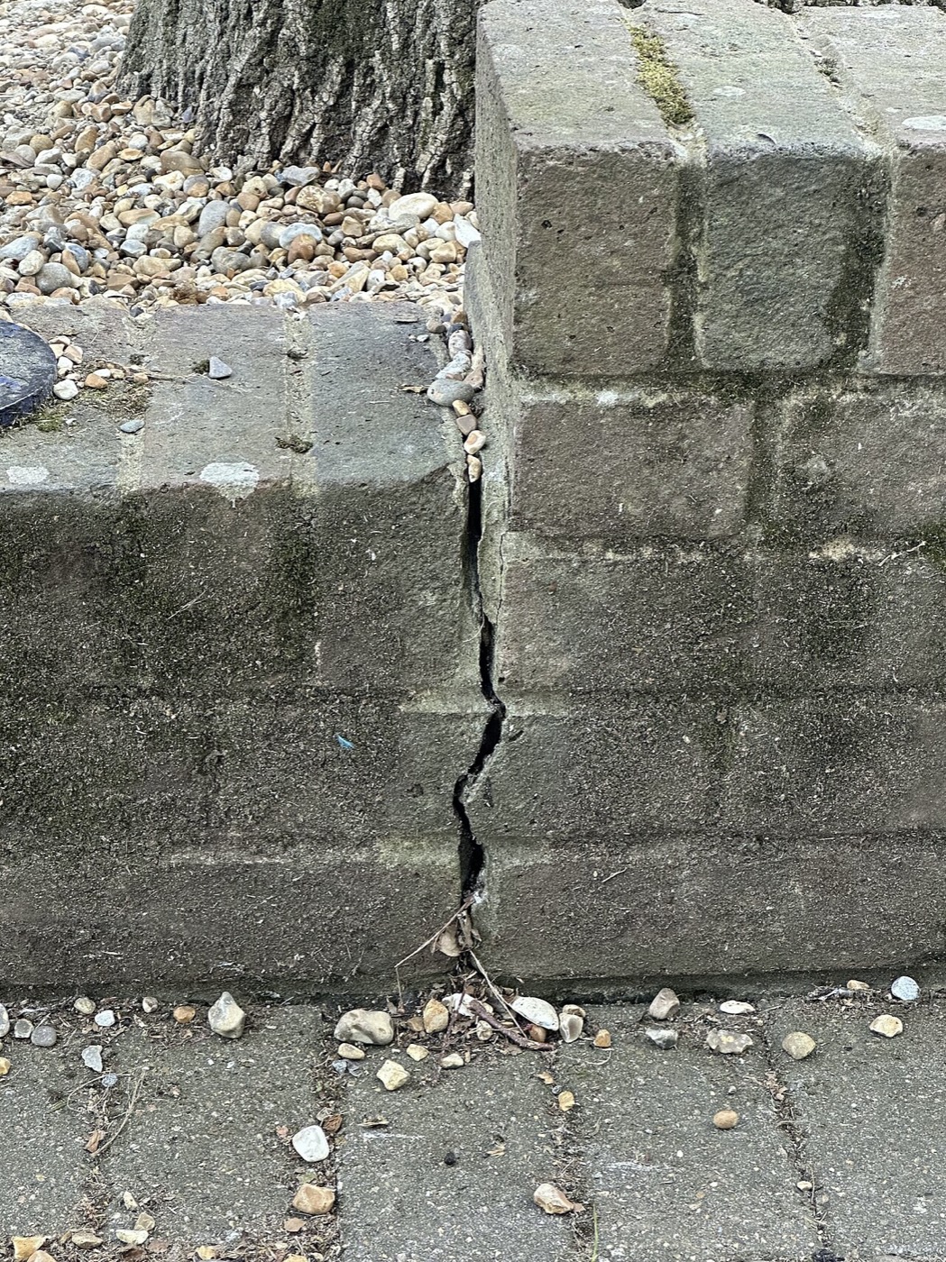
Concrete crack detection is the automated process of finding, measuring and grading cracks in concrete structures from inspection imagery. Computer vision segments each crack at pixel level, estimates its width in millimetres and ranks it by severity, so engineers review the cracks that matter rather than every survey photograph.
Concrete crack detection is the process of finding, measuring and grading cracks in concrete structures — bridges, tunnels, retaining walls, spillways and buildings — from inspection imagery rather than by eye alone. Computer vision now handles the first pass: it segments each crack at the pixel level, estimates its width in millimetres, and ranks it by severity so that engineers spend their time on the cracks that matter. The aim is not to replace the inspecting engineer but to turn thousands of survey photographs into a consistent, measurable defect record. This post explains what crack detection is, how a model grades a crack, and where uncertainty-aware computer vision fits into a safety-critical inspection programme.
What is concrete crack detection?
Concrete crack detection is the automated identification and measurement of cracks in concrete from images or video, producing a location, a width and a severity grade for each crack.
Not every crack means the same thing. A fine map-cracking pattern from early-age shrinkage is a durability question; a diagonal crack near a bridge support may be a sign of structural distress. Engineers grade cracks on width, orientation, length, spacing and whether the crack is active (moving) or dormant. Width is the number that anchors most of these judgements. Under BS EN 1992 (Eurocode 2), calculated crack widths are limited to between 0.2 mm and 0.4 mm depending on exposure class and member type, with 0.3 mm a common serviceability limit for reinforced concrete. So a crack width is not a cosmetic detail — it is the value that decides whether a crack breaches design criteria, and it is exactly what an inspection needs to record reliably.
Why grade cracks, not just find them?
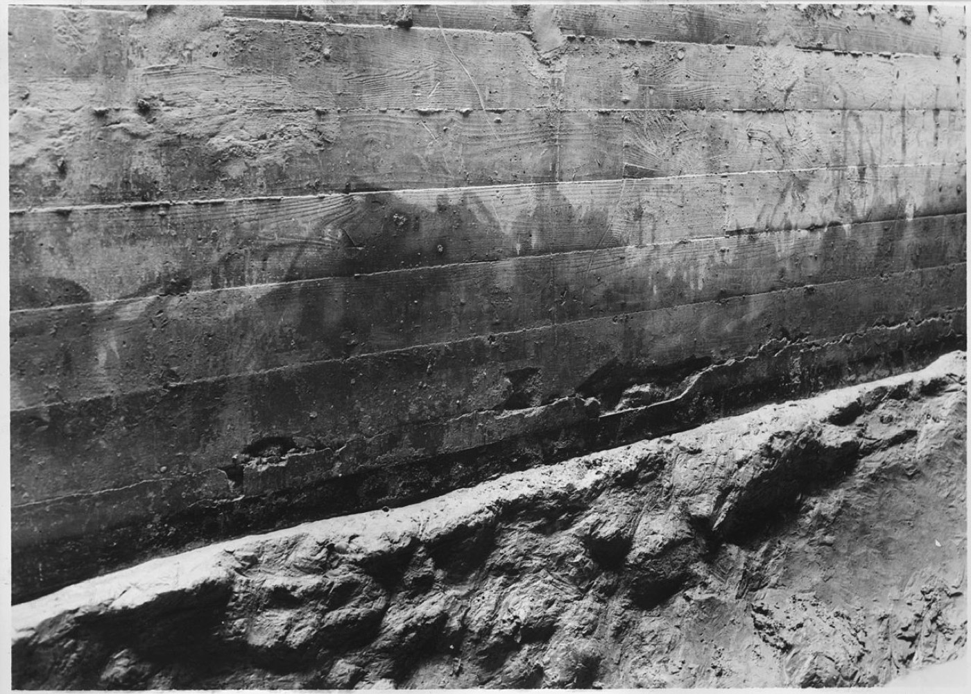
The value of an inspection lies in the grading. Spotting a crack is easy; deciding whether it is a durability concern, a serviceability issue or evidence of structural movement takes measurement and context. A useful detection pipeline reports, for every crack, its maximum and along-length width, its length, its orientation and its position on the element. That is what separates hairline shrinkage cracks from wider flexural or shear cracks.
For asset owners running formal inspection programmes this consistency is the point. National Highways' CS 450 sets General Inspections at 24-month intervals and Principal Inspections at longer intervals, and the international standard for the assessment of existing concrete structures, ISO 16311-2, treats cracking as one of the phenomena to be recorded and evaluated. A measurable, repeatable grade means this year's survey can be compared with the last one instead of being re-judged from scratch. The same approach underpins automated bridge inspection, where cracks and corrosion are the two defects most surveys are hunting for.
How does computer vision measure a crack?
Getting from a photograph to a graded crack takes four steps:
- Segmentation. The model marks which pixels belong to a crack, producing a thin mask that follows the crack along its path — far more precise than a bounding box.
- Skeletonisation and width. The mask is reduced to a centre-line, and the perpendicular distance across the mask gives the crack width in pixels at each point.
- Scaling to millimetres. Pixel width is converted to real units using a known reference — a scale target in shot, or the camera-to-surface distance from a drone survey or photogrammetry model. This crack width measurement is the digital equivalent of holding a crack-width comparator card against the surface.
- Grading. Width, length and orientation feed a severity score, so the output is a ranked register rather than a pile of unsorted detections.
Done well, this produces numbers an engineer can defend, tied to the imagery they came from.
Can you start crack detection with no labelled dataset?
The obstacle for most inspection teams is not the algorithm — it is training data. A model trained on one operator's bridge photos rarely transfers cleanly to another's tunnel imagery, and few asset owners hold thousands of labelled crack images. VisionEngine starts from an open-vocabulary baseline: you describe the defect in plain words — "longitudinal crack", "spalling", "corrosion staining" — and get a first detection pass with zero training images. That gives you a result to review on day one, rather than after a labelling programme that may never get funded.
Fewer, better labels through active learning
To move from a baseline to a tuned model you will label some images, but not thousands of them. Expert time is expensive, and asset access — scaffolds, rope access, confined-space entry, track possessions — is more expensive still. Active learning chooses the fewest, most informative images for an engineer to label: the ambiguous cracks near the model's decision boundary, not the hundredth obvious hairline. Labelling effort stays proportionate to the value it adds, which is what makes the approach realistic for teams that cannot spare weeks of specialist time.
Confidence where it is safety-critical
Concrete cracks are a safety-critical signal, and a detector that is quietly wrong is worse than no detector at all. VisionEngine attaches an uncertainty estimate to every detection, so the workflow can route only the low-confidence cases — a possible shear crack in poor light, an unusual pattern near a bearing — to a human, while high-confidence hairline cracks are logged automatically. That is the basis of risk-based review: an engineer's attention goes where the model is least sure, not spread evenly across every photograph in the survey.
It also underpins structural crack monitoring. Because each survey produces measured, uncertainty-tagged widths, you can compare surveys over time and flag the cracks that are widening rather than the ones sitting dormant. Change, not just presence, becomes something you can measure.
Fitting an existing inspection regime
Computer vision does not replace Eurocode assessment, tactile checks or the inspecting engineer's judgement — it front-loads the measurement. Photographs from a drone survey, pole camera or walkover are processed into a graded crack register that plugs into the reporting a team already produces for CS 450 or Network Rail examinations, as part of a broader automated visual inspection workflow. The same pipeline extends to tunnel and dam inspection, where access is harder and consistency matters even more.
The result is not fewer inspections but better-directed ones: consistent measurement across every image, and expert time concentrated on the cracks that genuinely need a trained eye.
Grade cracks automatically from photos. Run a free open-vocabulary baseline on your own inspection imagery and see the crack register VisionEngine produces — start with VisionEngine.
Frequently asked questions
Can AI replace a qualified inspector?
No. Computer vision is a screening and review layer, not a replacement for engineering judgement. It flags and grades cracks across large image sets and routes the uncertain calls to a qualified inspector, who makes the structural assessment. The aim is to concentrate expert attention where it adds most value, keeping a human in the loop.
How much labelled data do you need to start?
None to begin with. VisionEngine runs an open-vocabulary baseline on your own images with no training data: you describe the defect in plain words and get a first detection pass on day one. You then review a small number of the most uncertain cracks through active learning to improve the model, rather than labelling thousands of images upfront.
How does computer vision measure crack width?
Where the image has a known scale, the model segments the crack at pixel level, reduces the mask to a centre-line and measures the perpendicular width in pixels. That pixel width is converted to millimetres using a scale target in shot or the camera-to-surface distance, giving a defensible measurement rather than only flagging that a crack exists.
Why does crack width matter for grading severity?
Width is the number that anchors most crack assessments. Under BS EN 1992 (Eurocode 2), calculated crack widths are limited to between 0.2 mm and 0.4 mm depending on exposure class and member type, with 0.3 mm a common serviceability limit. A recorded width decides whether a crack breaches design criteria, so it is what an inspection must capture reliably.